5G is effective in bringing high data rates. It requires efficiency for the power amplifier. We can understand and calculate PA’s efficiency accordingly. Radio communication is improving steadily and overall system performance with 5G. The higher performance causes pressure on power consumption.
A recent report came out which showed information related to the power consumption of the standard base station of 5G. The data records revealed that the power consumption is around 7kW to 12kW for the LTE base station of 5G connectivity. It is for the 5 toasters which use the additional power.
A single toaster is of 2-slice which consumes around 1000W power in it. System designers are fret of the power consumption. The battery-powered devices include mobiles.
The talk time in the phone depends on its battery capacity. The lower power means a longer operating time for the phones. The power usage in the station depends on the cost of energy used in the network. The waste power in the device generates heat, which should be dissipated.
Understanding the concept of Power Amplifier (PA)

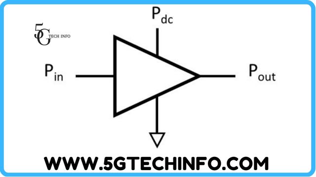
A power Amplifier (PA) is a significant power consumer occurring in a wireless system. Therefore, it is important to understand the concept of the power amplifiers. The respective figure 1 shows the PA producing the power of (Pout). Additionally, it is based on the input power (Pin) and supplied power in DC (Pdc).
Engineers use the amplifier power for depicting a concept.
GdB=10log (Pout/Pin)
Power-Added Efficiency (PAE) expresses the overall efficiency related to the power amplifiers that cause the effect on the input power.
PAE=Pout-Pin/Pdc
PAE is expressed as a percentage in it. Example: The power amplifier is of the power output power of 10W. The input power is 0.5W and the DC power is 30W. We get the PAE= (10-0.5)/30=32%. The power gain that emerged in this amplifier is Gdb=10log (10/0.5) =13 db.
Another parameter to check the amplifier efficiency is power efficiency. Then, at that time, the requirement is to ignore the input power. The efficiency is defined in the output power and supplied DC power.
PE=Pout/Pdc
It is when the power efficiency is focused on the single transistor. It is known as drain efficiency (FET device) or collector efficiency (Bipolar transistor). The usage reflects that the DC power is determined by measuring the drain or collector and multiplied by the DC power supply voltage. It is important to note that the gain of the amplifier is at a higher rate. The input fades in importance and causes PAE that is roughly the same as PE.
Peak-to-Average Power Ratio
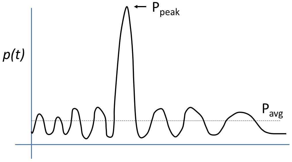
Variation is in the input signal, which can affect the practical efficiency of the power amplifiers when used in it. Modern digital modulation methods can result in the signals. The variation occurs in these signals used in the instantaneous power. Figure 2 shows the instantaneous power levels of the signal, which comes with the peak power (Ppeak) compared to the average power (Pavg). The way to describe the peakiness which is in the waveform is the peak-to-average ratio (PAPR) expressed in decibels.
PAPR=10 log (Ppeak/Pavg)
Amplifier designers use constant power levels, which tweak the amplifier to get the best performance. The respective figure 3 shows the PE function of the output power in the typical power amplifier. The amplifier tends to drop at low power levels. The purpose of the curve shape is important in the specific values. The PA can handle the operative efficiency that would like the amplifier to operate. The PAPR signal causes the movement of the operating point from left to right. Then, the peak power does not overdrive the amplifier.

Availability of design options
The backing off is on the operating point and the amplifier’s output power is the solution to the problem of the high PAPR. Still, the amplifier efficiency suffers at that time. The RF engineers developed two methods that can do the adjustment in the operating amplifier behavior in real-time for improving efficiency. These two methods proposed in the 1930s. These commonly designed approaches are used extensively in the 21 century. The two methods are as follows:
- Envelope tracking amplifier: The input signal controls the power supply voltage of the amplifier.
- Doherty amplifier: It is a two-path amplifier responding to the peak in the input signal on the requirement.
ALSO READ: What is Chat GPT?